Features
and Layout
The
GA-8PE667 Ultra 2 is the most features packed 845PE motherboard from Gigabyte.
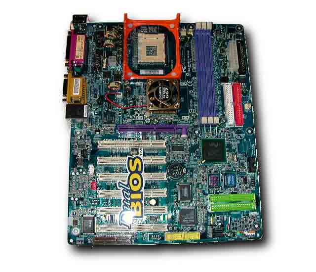
The GA-8PE667 Ultra 2 sports more features and a different layout than the
original GA-8PE667 Ultra. As you can see the PCB is Blue and should look
great in a windowed case. All of Gigabytes new high-end motherboards sport
blue PCBs. You would think with so many on-board components the layout would
be cramped, but somehow Gigabyte was able to keep the layout clean and still
provide six PCI slots. A lot of highly integrated boards have fewer PCI slots.
Overall Gigabyte did a great job with the layout.
The
first thing you will notice is the rather large heatsink and fan on the Northbridge.
Active cooling on the Northbridge is always a good idea, especially when overclocking.
The heatsink and fan feel high quality; the gold color really adds a nice
touch.
The
GA-8PE667 Ultra 2 sports two RAID chips, the Promise 20276 and the Silicon
Image Sil3112A. The Silicon Image Sil3112A supports two Serial ATA devices
at speeds up to 150MB/Sec and supports RAID 0 and 1. We will be seeing Serial
ATA hard drives very soon; with the GA-8PE667 Ultra 2 youll be ready for
them. The Promise 20276 chip has been around for some time now and supports
current IDE drives at speeds up to 133MB/s. It has support for RAID 0 and
1. Support for both Serial and IDE RAID is not only very impressive, its
useful.
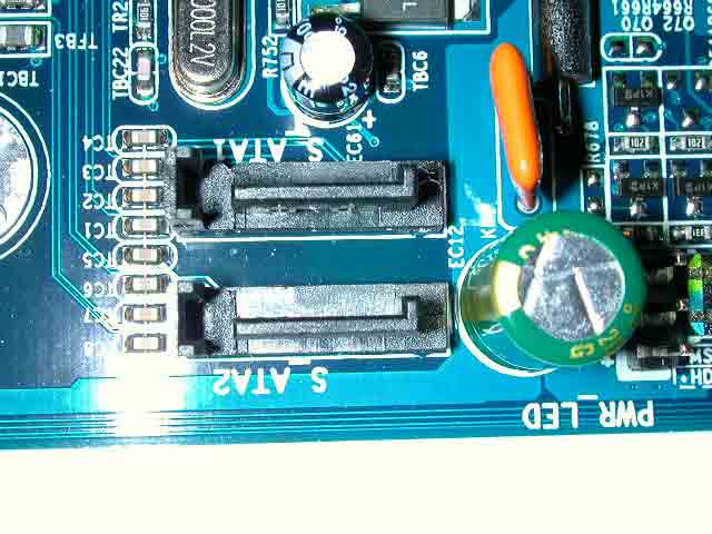
Gigabyte
placed the Serial ATA and IDE RAID connectors at the bottom right area of
the board. As you can see the Serial ATA connectors are very small compared
to IDE connectors. The RAID IDE connectors are mounted horizontally. You
can only connect one device per channel with Serial ATA. You can connect
up to four IDE hard drives to the Promise RAID.
Its
nice to see that the 20pin main power connector is located in the upper right
area of the board. Some manufacturers place the 20pin power connecter next
to the CPU socket area. When the power connector is placed badly like this
the power cable can affect airflow and sometimes even hit the fan. The floppy
drive connector is mounted vertically next to the power connector. Below
that we find the two ATA100 connectors powered by the Southbridge, also mounted
vertically.
The
area around the CPU socket is clean; you should have no problems installing
a larger heatsink like the Alpha 8942 and Swiftech MCX4000. The heatsink
mounting bracket included is a cool orange color. When installing larger
heatsinks we found that the motherboard did bend slightly. This is a common
problem when using larger heatsinks. It would be nice to see some kind of
reinforcement mechanism used to prevent this from happening. As you can see
the 12V connector is placed to the left of the socket.
When
a BIOS flash fails you can permanently destroy your motherboard. Gigabytes
DualBios technology is definitely a great feature of the GA-8PE667 Ultra 2.
The secondary Bios acts as a hot-spare and will take over almost immediately
when the main system Bios fails. As you can see there are physically two
Bios chips on the board.
Onboard
Ethernet is very common nowadays and we are starting to see Gigabit Ethernet
Controllers integrated onto higher end boards. The GA-8PE667 Ultra 2 uses
Intels 82540EM Gigabit Ethernet chip. The 82540EM chips supports 1000 Mb/s,
100, Mb/s and 10Mb/s speeds. Both the MAC and PHY layer are integrated into
this compact chip. It connects directly to the PCI bus and is designed to
deliver high performance and use low power.
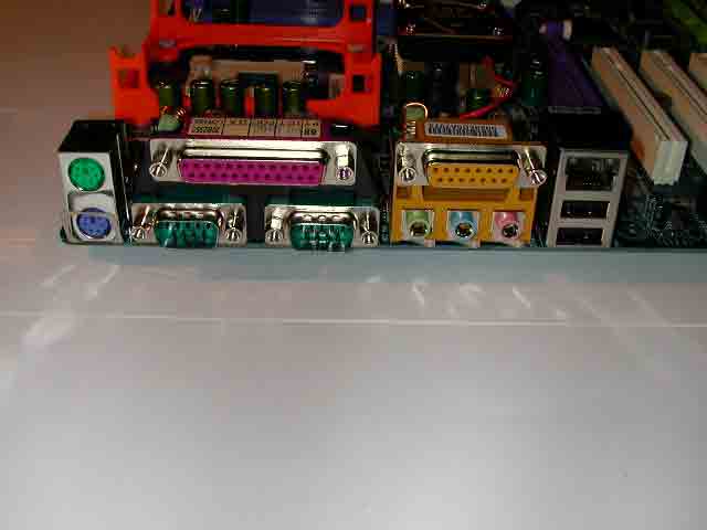
Here
you can see the PS/2 Mouse and Keyboard Connectors, Parallel Port, Serial
Ports, Game Port, Audio Connectors, USB 2.0 and LAN connector. The GA-8PE667
Ultra 2 uses a standard back plate design. This is nice because most ATX
I/O panels will work.
The
ALC 650 codec chip from RealTek is used on the GA-8PE667 Ultra 2. Although
this is not the best solution available, it does provide more than decent
sound quality. I could barely tell the difference in quality between the
ALC 650 and my Sound Blaster Live. The GA-8PE667 Ultra 2 supports 6 channel
audio in two different modes; basic mode and advanced mode. In basic mode
you use the back audio panel to connect the audio output. In advanced mode
you use the included Audio Combo Kit. The Combo Kit also has jacks for RCA
and SPDIF. You can also configure the audio in a 2 channel or 4 channel configuration
with the audio software provided.
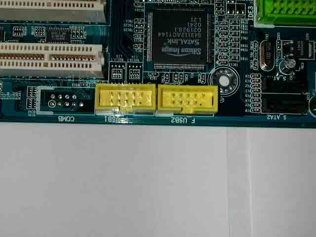
The
USB Kit included provides 4 additional USB 2.0 ports. The kit connects to
the two yellow connectors shown above. Having a total of six USB 2.0 ports
is definitely useful if you use a lot of external devices. We would have
also liked to see a Fire Wire chip integrated onto the board.
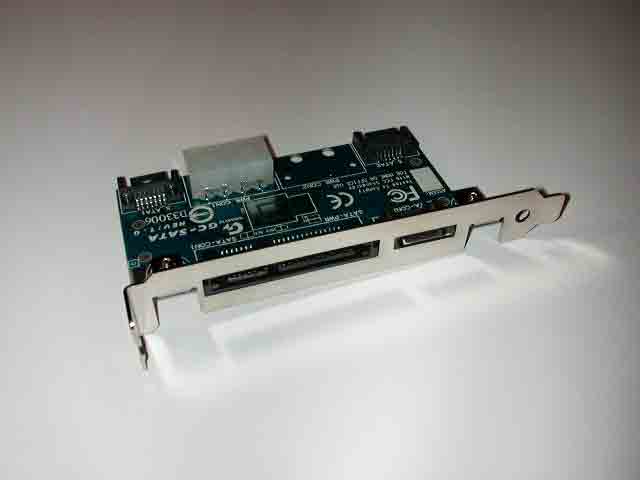
Gigabyte
includes their new GC-SATA Card with this motherboard. This card allows you
to connect external SATA devices. It comes with one Serial ATA cable and
a power cable for Serial ATA hard drives. I think this is a very interesting
device and will be useful in the near future. It comes with documentation
and step by step instructions for installation.
Its
the small things that count! Gigabyte has color coded the Power switch, Reset
switch, HDD LED, Power LED and PC speaker pins. This really makes things
much easier when making connections. I sure hope that more motherboard vendors
color code their pins. They have also rounded the edges of the PCB. This
will help prevent motherboard edges from cracking when bumped or dropped.
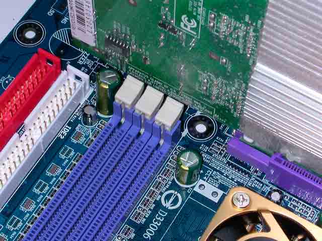
As
you can see the video card comes very close to the RAM slots. However, we
were still able to install and remove RAM with the video card in place.
The
Bios
The
GA-8PE667 Ultra 2 uses an Award Bios. I am going to skip over the standard/basic
Bios features and move onto the good stuff!

The
PC Health feature displays the Voltages, Temps, Fan Speeds, and also allows
you to set warning fan speeds and temps. There is also a case open status.
As you can see from the voltage readings, our motherboard was slightly under-volting
the system. We did not notice any system stability issues while running the
system under full load. The system was stable as a rock. We still do hope
this issue is addressed in future Bios updates from Gigabyte.
You
must press (Ctrl+F1) to access the more advanced Bios settings. I can understand
why they hide the advanced features; they dont want novice users messing
with settings that could cause harm to the system if not used correctly.
Within
the Advanced Chipset Features section of the Bios we find the memory settings
and AGP aperture size. I usually set the AGP aperture size to 1/4 my system
memory. The memory options are: CAS Latency Time, Active to Precharge Delay,
DRAM RAS# to CAS# Delay, DRAM RAS# Precharge, Refresh Mode Select and Delayed
Transaction. Before changing memory timings its important to make sure your
memory can handle those timings. Setting the wrong timings can result in
system instability and maybe even hardware damage. Although Gigabyte could
have added more memory settings, the settings they offer should be adequate
for most tweakers.
In
the Frequency/Voltage Control section we find all the settings necessary to
overclocking the system. The FSB can be adjusted all the way up to 355MHZ.
However a FSB of 355 (355x4=1420!!) would never be possible on a Pentium 4
system. You are able to fix the PCI and AGP frequency; this can be very helpful
when overclocking. Being able to fix the PCI and AGP means when you overclock
the front side bus the PCI will still be running at 33MHZ and the AGP will
still be running at 66MHZ.
The
Host/DRAM clock ratio can be set to either 2.66 or 2.0. If you are running
a Pentium 4 with a FSB of 100MHZ (100x4=400MHZ) then the 2.0 setting would
give you a memory speed of 200MHZ (2.0x100). The 2.66 setting would give
you a memory speed of 266MHZ (100x2.66). So, if you are running an older
Pentium 4, you are limited to the 266MHZ memory. If you are running a newer
133MHZ (133x4=533) FSB Pentium 4 the 2.0 setting would give you a memory speed
of 266MHZ (2.0x133) and the 2.66 setting would give you a memory speed of
333MHZ (2.66x133). Of course you can always push the FSB higher to get a
greater memory clock. *Remember, as the FSB (Front Side Bus) speed increases,
so does the memory speed.
The
AGP voltage can be set up to 1.8V. The DIMM voltage can be set up to 2.8V.
I always keep the DIMM voltage under 2.8V to prevent any possible damage.
The
motherboard manual says the CPU voltage can go up to 1.850V. Unfortunately
we found that the Bios would only allow a maximum V-Core of 1.725V. This
issue should be fixed in future Bios updates.