 |
The Layout / Features

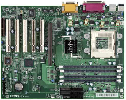
As you might have already noticed, the positioning of the HDD/FDD connector
ports is very comfortable because they are out of the way of all components.
This board features two 40-pin IDE connectors marked as IDE1 and IDE2. Each
connector supports two IDE devices.
The RIMM slots do not interfere with video card (AGP slot). This little
problem has been noticed on several of today’s motherboards and generally
results in unpleasant experiences and I’m happy to say that the P4TSA is not
a part of this category.
The expansion of the P4STA is considered MAXIMAL for an 850 solution (PCI/ISA/CNR/AGP).
It includes five PCI slots continuing with a CNR slot. The P4TSA features
an AGP PRO port compared to the early reviewed 850 solutions from DFI Corporation
that featured a standard AGP port.
The power supply connector is comfortably located on the right edge of the
board, this is another positive point about the P4TSA design as the power
cables will not run over the memory and CPU which would potentially block
airflow. The power supply connector meets the SSI (Superset ATX) 24pin specification;
however, it also supports an ATX 20pin connector. Thus, both 20pin ATX and
24pin SSI connectors can be installed on the P4TSTA as long as the PS connector
is correctly oriented.
SM opted to take advantage of the onboard AC97 sound present on the ICH2.
This particular codec is very similar to the Sound-Blaster 16 card and should
satisfy most of the office users. However, if you are playing a lot of games
and/or use a multi-channel sound system, you would be better off with a normal
high-end audio card such as the SBLIVE. The implanted audio solution features
two different internal audio connectors (CD-in/CD-in) on the PCB. These connectors
allow you to receive stereo audio input from sound sources such as CD-ROM
drives and TV Tuners.
Overclocking your P4 Processor with the P4STA will unfortunately not be possible
because the board doesn’t feature any Front Side Bus adjustments.
|
|